


Bently Nevada
📢 100% genuine, extensive in-stock inventory, fast shipping!
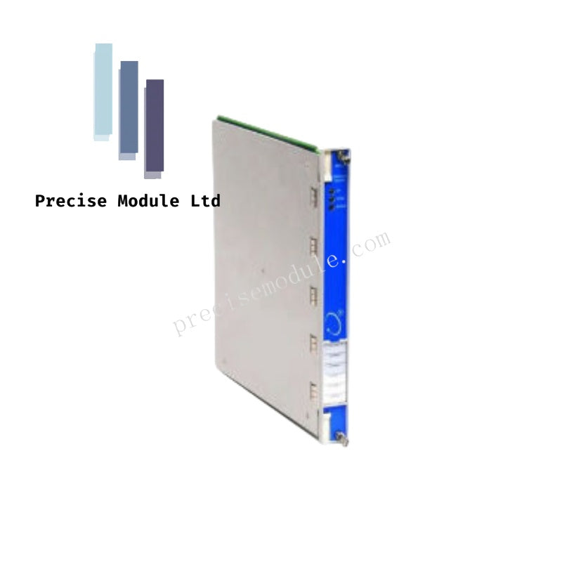
Bently Nevada 125712-01 3500/32 4-Channel Relay Module
Bently Nevada 125712-01 3500/32 4-Channel Relay Module
Manufacturer: Bently Nevada
Condition:in Stock
Product Type: Relay Module
-
Product Origin: USA
Payment:T/T, Western Union
-
Weight: 750g
Shipping port: Shanghai/Yiwu/Shenzhen
Warranty: 12 months
Share
Bently Nevada 125712-01 3500/32 4-Channel Relay Module
The Bently Nevada 125712-01 serves as the primary 3500/32 4-Channel Relay Module utilized to execute programmatic voting logic and emergency trip contact deployment across Bently Nevada 3500 platforms. The full-height hardware assembly integrates directly with the system backplane, receiving digital alarm statuses from internal monitor cards to actuate independent physical isolation circuits.
Hardware Specifications
| Parameter | Specification |
|---|---|
| Model | 125712-01 |
| Brand | Bently Nevada |
| Origin | USA |
| Weight | 0.75 kg |
| Dimensions | 2.6 cm x 25.2 cm x 24.1 cm |
| Operating Temp | -30 to +65 deg C |
| Power Consumption | 5.8 W typical |
| Tariff Code | 8537101190 |
| Module Type | 4-Channel Relay Module |
| Environmental Sealing | Epoxy-sealed |
| Arc Suppressor | 250 Vrms, installed as standard |
| Contact Life | 100,000 cycles at 5 A, 24 Vdc or 240 Vac |
| Maximum Switched Voltage | 250 Vac |
| Maximum Switched Current | 2 A |
| Maximum Switched Power | 450 VA |
| Humidity Limit | 95%, non-condensing |
Alarm Drive Logic and Signal Suppression Matrix
The internal architecture of the Bently Nevada 125712-01 features programmable Alarm Drive Logic gates supporting complex AND/OR voting topologies. In high-density Turbomachinery Instrumentation (TSI) environments, the relay processor scans the internal rack bus to evaluate alert and danger bits across discrete channels. To prevent false trip execution caused by transient mechanical spikes or eddy-current probe cross-talk, the processing engine incorporates digital signal validation filters. This matrix ensures that the output contacts remain stable during rotor dynamics shifts and gap voltage validation anomalies, executing open or closed state transitions only when verified voting thresholds are breached.
Frequently Asked Questions
Q: Can this relay card be installed in any slot within the 3500 rack?
A: Yes. Any number of 125712-01 modules can be positioned in any of the standard I/O slots situated directly to the right of Slot 1 (the Rack Interface Module position).
Q: Are the contacts on this module dry or powered?
A: The relay outputs are potential-free, dry contacts rated up to 250 Vac. Field engineers must supply the appropriate external wetting voltage within the specified contact power thresholds.
Q: What is the purpose of the factory-installed arc suppressors?
A: The onboard 250 Vrms arc suppressors absorb inductive voltage spikes produced when interrupting inductive field loads (such as solenoid valves), protecting the relay contacts from premature degradation.
Field Installation Guidelines
- Chassis Alignment: Slide the full-height assembly into the designated slot guides. Ensure the rear gold-fingered connectors seat firmly into the backplane before torquing the front panel fasteners to prevent terminal stress.
- Terminal Wiring Containment: Maintain separation between low-voltage sensor cables and high-voltage relay contact wiring within the field wiring ducts to eliminate electromagnetic noise coupling.
- Logic Download Verification: After physical installation, the user must deploy the 3500 Rack Configuration Software to bind the relevant monitor channels to the relay voting matrix; unconfigured channels will default to an inactive state.
Hot Tags :


- Choosing a selection results in a full page refresh.
- Opens in a new window.