


Bently Nevada
📢 100% genuine, extensive in-stock inventory, fast shipping!
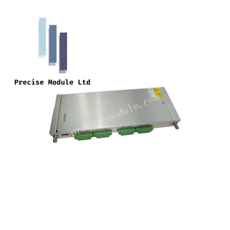
Bently Nevada 125768-01 3500 Series Rack Interface I/O Module
Bently Nevada 125768-01 3500 Series Rack Interface I/O Module
Manufacturer: Bently Nevada
Condition:in Stock
Product Type: Series Rack Interface I/O Module
-
Product Origin: USA
Payment:T/T, Western Union
-
Weight: 450g
Shipping port: Shanghai/Yiwu/Shenzhen
Warranty: 12 months
Share
Bently Nevada 125768-01 3500 Series Rack Interface I/O Module
Configured for rack configuration and machinery data retrieval in 3500 Series Machinery Protection Systems, the Bently Nevada 125768-01 (125768-01 Rack Interface I/O Module) provides direct physical/electrical execution.
Hardware Specifications
| Parameter | Specification |
|---|---|
| Model | 125768-01 |
| Brand | Bently Nevada |
| Origin | USA |
| Weight | 0.45 kg |
| Dimensions | 2.5 x 11.2 x 24.2 cm |
| Operating Temp | -40 to +85 deg C |
| Power Consumption | 3.5 W typical |
| Power Supply | 24 V DC |
| Module Current | 145 mA typical |
| Digital Inputs | 8 x 24 V DC |
| Accuracy | +/-0.1 % of span @ 25 deg C |
| Storage Temp | -55 to +85 deg C |
| Humidity | 5 - 95 % RH non-condensing |
| Tariff Code | 8537101190 |
Rotor Dynamics and Cross-Talk Suppression Architecture
The module acts as the core communication path for transferring digitized rotor dynamics data from individual monitor modules to external processors. The internal bus interface executes data transmission while maintaining high cross-talk suppression across the backplane lines. For Triple Modular Redundant (TMR) architectures, the interface supports continuous monitor channel comparison. It tracks the gap voltage validation metrics across three redundant monitors, flagging an explicit system event if one channel deviates beyond the configured percentage limit relative to the remaining two channels.
Frequently Asked Questions
Q: What rack slot position is mandatory for the 125768-01 module?
A: The module must be installed exclusively in slot 1 of the 3500 rack, positioned directly adjacent to the power supply modules.
Q: Does a hardware failure of this interface module interrupt the active machinery protective trip path?
A: No. The module executes configuration and data extraction tasks but is completely isolated from the critical monitoring path, ensuring a module failure has no impact on normal trip loop execution.
Field Installation Guidelines
- Slot Allocation: Verify that the chassis slot is clean and free of debris. Insert the module into slot 1, aligning the board edge carefully with the chassis guides to prevent backplane pin misalignment.
- Shield Grounding: Connect the digital input signal shields to the dedicated rack ground bus bar. Maintain a clean separation between these signal runs and high-voltage AC cabling to prevent induced noise.
- Terminal Fastening: Secure all field wiring to the terminal block using calibrated torque tools to prevent connection degradation caused by continuous industrial machinery vibration.
Hot Tags :


- Choosing a selection results in a full page refresh.
- Opens in a new window.