


Bently Nevada
📢 100% genuine, extensive in-stock inventory, fast shipping!
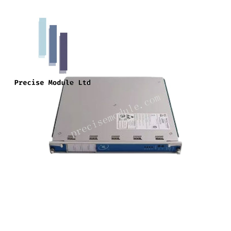
Bently Nevada 149986-01 3500/33 16-Channel Relay Module
Bently Nevada 149986-01 3500/33 16-Channel Relay Module
Manufacturer: Bently Nevada
Condition:in Stock
Product Type: 16-Channel Relay Module
-
Product Origin: USA
Payment:T/T, Western Union
-
Weight: 750g
Shipping port: Shanghai/Yiwu/Shenzhen
Warranty: 12 months
Share
Bently Nevada 149986-01 3500/33 16-Channel Relay Module
The Bently Nevada 149986-01, also cataloged as the 3500/33 16-Channel Relay Module, serves as the primary 3500/33 16-Channel Relay Module utilized to execute programmable voting logic and hardware contact switching across Bently Nevada 3500 Machinery Protection System platforms.
Hardware Specifications
| Parameter | Specification |
|---|---|
| Model | 3500/33 149986-01 |
| Brand | Bently Nevada |
| Origin | USA |
| Weight | 0.75 kg |
| Dimensions | 2.6 x 25.2 x 24.1 cm |
| Operating Temp | Standard industrial range for 3500 series backplanes |
| Power Consumption | 5.8 watts typical |
| Product Type | 16-Channel Relay Control Module |
| Max Switched Current | 5 A |
| Max Switched Voltage | 125 Vdc (30 Vdc nominal) |
| Min Switched Current | 100 mA @ 5 Vdc |
| Relay Arc Suppressor | 250 Vrms Installed as standard |
| Relay Contact Life | 10,000 cycles |
| Slot Requirements | 1 full-height front slot (requires 1 full-height rear I/O slot) |
Eddy-Current Probe Scaling and Rotor Dynamics
The 16-channel relay module acts as the physical execution layer for machinery monitoring variables derived from adjacent vibration and position cards. When eddy-current probe scaling detects deviations in peak-to-peak vibration or rotor dynamics displacement, the backplane drives alarm logic flags to this module. Independent contact structures vote on system statuses, tracking sensor baseline variations relative to a targeted -10 VDC gap voltage validation center line. Internal cross-talk suppression paths ensure that fast relay switching actions do not induce capacitive noise or cross-talk spikes onto surrounding low-voltage sensor input backplane buses.
Frequently Asked Questions
Q: Where can this relay module be placed within the 3500 chassis system?
A: The 3500/33 module can be installed in any available full-height slot located to the right of the Transient Data Interface (TDI) Module.
Q: What logic components can be used to program the independent relay outputs?
A: Each relay features independent Alarm Drive Logic configurable via AND and OR operators using alert/danger statuses, Not-OK states, or combinations of measured variables from any monitor channel.
Field Installation Guidelines
- Arc Suppression Verification: Ensure external wiring loads conform to the built-in 250 Vrms maximum arc suppressor parameters to prevent contact degradation under heavy inductive loads.
- Slot Positioning Constraints: Always align the front 149986-01 module exactly with its corresponding rear full-height 16-channel relay I/O module before securing the retention screws.
- Current and Voltage Restrictions: Maintain field loop demands between the minimum 100 mA at 5 Vdc threshold and the maximum 5 A switching capacity limits.
- Wiring Routing Isolation: Route high-voltage relay contact circuits through distinct conduit pathways separated from low-voltage eddy-current probe field lines to maintain signal isolation.
Hot Tags :


- Choosing a selection results in a full page refresh.
- Opens in a new window.