


Bently Nevada
📢 100% genuine, extensive in-stock inventory, fast shipping!
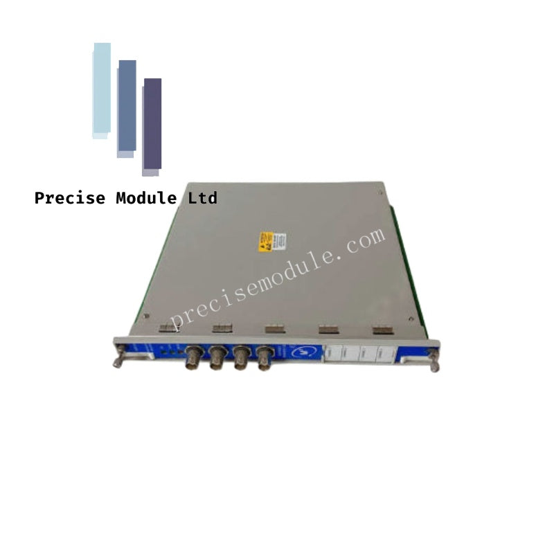
Bently Nevada 176449-04 3500/45 Position Monitor Module
Bently Nevada 176449-04 3500/45 Position Monitor Module
Manufacturer: Bently Nevada
Condition:in Stock
Product Type: Position Monitor Module
-
Product Origin: USA
Payment:T/T, Western Union
-
Weight: 820g
Shipping port: Shanghai/Yiwu/Shenzhen
Warranty: 12 months
Share
Bently Nevada 176449-04 3500/45 Position Monitor Module
The Bently Nevada 176449-04 serves as the primary 3500/45 Position Monitor Module utilized to execute continuous axial displacement, casing displacement, and valve position monitoring across Bently Nevada 3500 platforms. The 4-channel instrument processes mechanical displacement data from external transducers to safeguard rotating machinery against destructive structural contact and thermal expansion stress.
Hardware Specifications
| Parameter | Specification |
|---|---|
| Model | 176449-04 |
| Brand | Bently Nevada |
| Origin | USA |
| Weight | 0.82 kg |
| Dimensions | 2.5 cm x 25.8 cm x 12.0 cm |
| Operating Temp | -30 to +65 deg C |
| Power Consumption | 7.7 W maximum |
| Tariff Code | 8537101190 |
| Module Type | Position Monitor Module |
| Input Channels | 4 fully programmable channels |
| Supported Transducers | Proximity probes, RPTs, AC LVDTs, DC LVDTs, Rotary Potentiometers |
| Humidity Limit | 95%, non-condensing |
Eddy-Current Probe Scaling and Rotor Dynamics Integration
The internal processing logic of the Bently Nevada 176449-04 features adaptive eddy-current probe scaling to precisely track complex mechanical geometries during operational transitions. In applications such as differential expansion or axial thrust position monitoring, the module executes real-time gap voltage validation (-10 VDC targets) to verify the physical position of the rotor relative to stationary components. Cross-talk suppression algorithms isolate the positioning channels from high-frequency interference generated by adjacent radial vibration probes, preventing false alarm generation during peak thermal growth or rapid rotor dynamics fluctuations.
Frequently Asked Questions
Q: How is the module configured to switch between AC LVDT and proximity transducer inputs?
A: Transducer selection is controlled through the 3500 Rack Configuration Software. However, hardware compatibility depends strictly on the physical I/O module fitted to the rear of the rack, as AC LVDTs require external excitation tracking circuitry not present on standard proximity I/O cards.
Q: What specific position monitoring methodologies can be programmed into this module?
A: Each of the four channels can be independently configured for Axial (thrust) Position, Case Expansion, Valve Position, or various differential expansion profiles, including Standard Single Ramp, Non-standard Single Ramp, Dual Ramp, and Complementary Differential Expansion.
Field Installation Guidelines
- Chassis Slot Placement: Ensure the rack power supply is deactivated prior to module installation. Slide the 176449-04 monitoring card into any available standard I/O slot to the right of slot 1, pushing firmly until the backplane connectors seat completely.
- Transducer Cable Shielding: Terminate all transducer cable shields strictly at the designated chassis ground terminal on the rear I/O module. Ground loops or unshielded signal runs will compromise gap voltage validation and introduce measurement drift.
- LVDT Excitation Matching: When deploying AC LVDTs, field technicians must verify that the excitation frequency and voltage levels match the transducer manufacturer's technical specifications to prevent linear scaling errors.
Hot Tags :


- Choosing a selection results in a full page refresh.
- Opens in a new window.