


Bently Nevada
📢 100% genuine, extensive in-stock inventory, fast shipping!
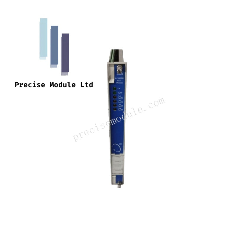
Bently Nevada 3500/32 125712-01 4-Channel Relay Module
Bently Nevada 3500/32 125712-01 4-Channel Relay Module
Manufacturer: Bently Nevada
Condition:in Stock
Product Type: 4-Channel Relay Module
-
Product Origin: USA
Payment:T/T, Western Union
-
Weight: 750g
Shipping port: Shanghai/Yiwu/Shenzhen
Warranty: 12 months
Share
Bently Nevada 3500/32 125712-01 4-Channel Relay Module
The Bently Nevada 3500/32 125712-01, also cataloged as the 4-Channel Relay Module, operates as a dedicated hardware component for executing voting logic and alarm drive functions within 3500 Machinery Protection System racks.
Hardware Specifications
| Parameter | Specification |
|---|---|
| Model | 3500/32 125712-01 |
| Brand | Bently Nevada |
| Origin | USA |
| Weight | 0.75 kg |
| Dimensions | 2.6 x 25.2 x 24.1 cm |
| Power Consumption | 5.8 Watts typical |
| Contact Life | 100,000 cycles at 5 A |
| Max Switched Voltage | 250 VAC |
| Operating Temp | -30 deg C to +65 deg C |
Alarm Logic & Relay Control
The 3500/32 module facilitates machinery protection by providing four independent relay outputs, configurable via the 3500 Rack Configuration Software. Each relay supports fail-safe state execution by utilizing programmable voting logic (AND/OR logic gates). The module integrates galvanic isolation for internal logic circuits and includes standard arc suppressor components (250 Vrms) to extend contact longevity. Logic mapping allows the relays to trigger based on Alert/Danger statuses, Not-OK conditions, or Proportional Programmable Logic (PPL) inputs derived from any combination of monitor channels within the rack.
Frequently Asked Questions
Q: Can the 3500/32 relay module be placed in any rack slot?
A: Yes. This module can be installed in any available slot to the right of the Transient Data Interface (TDI) module within a standard 3500 rack.
Q: Are the internal relay contacts protected against inductive load switching?
A: Yes. Every relay is factory-equipped with a 250 Vrms arc suppressor as a standard feature, which minimizes contact pitting when switching inductive loads such as solenoid valves or alarm annunciators.
Field Installation Guidelines
- Module Seating: Insert the module into the designated rack slot and verify the backplane connector is fully engaged. Secure the front panel release levers to ensure long-term mechanical stability.
- Wiring Termination: Use appropriate gauge wire for relay outputs. Given the 450 VA maximum switched power limit, ensure wire sizing matches the expected load current to prevent thermal degradation at the terminal block.
- Configuration: Utilize the 3500 Rack Configuration Software to establish the required voting logic. Verify the logic behavior by simulating a channel alarm condition during the commissioning phase to confirm the relay state changes as expected.
- Environmental Protection: The module is epoxy-sealed; however, ensure the rack installation site maintains a non-condensing humidity environment below 95% to prevent potential corrosion of external terminal connections.
Hot Tags :


- Choosing a selection results in a full page refresh.
- Opens in a new window.