


Bently Nevada
📢 100% genuine, extensive in-stock inventory, fast shipping!
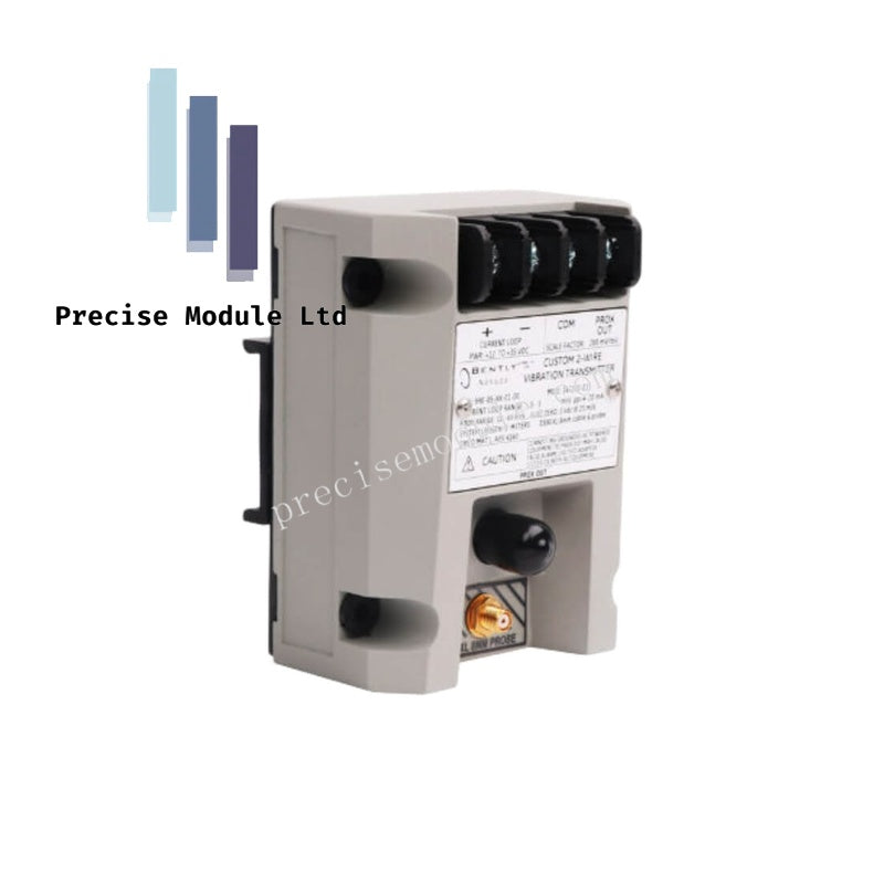
Bently Nevada 990-04-70-02-00 Vibration Transmitter
Bently Nevada 990-04-70-02-00 Vibration Transmitter
Manufacturer: Bently Nevada
Condition:in Stock
Product Type: Vibration Transmitter
-
Product Origin: USA
Payment:T/T, Western Union
-
Weight: 440g
Shipping port: Shanghai/Yiwu/Shenzhen
Warranty: 12 months
Share
Bently Nevada 990-04-70-02-00 Vibration Transmitter
The Bently Nevada 990-04-70-02-00, also cataloged as the 990 Vibration Transmitter, operates as a dedicated hardware component for converting proximity probe signals into a proportional 4-20 mA loop-powered output within machinery control and protection systems. The two-wire device conditions raw eddy-current inputs from a 3300 NSv proximity probe into peak-to-peak vibration amplitude values.
Suffix Breakdown & Model Matrix
The full part number designates specific factory configurations for scaling, cable length, mounting, and certifications:
- 04: Full-scale option rated for 0-4 mils pp (0-100 um pp).
- 70: System length option specified for 7.0 meters (23.0 feet).
- 02: Mounting option configured for bulkhead screws.
- 00: Agency approval option designated as not required.
Hardware Specifications
| Parameter | Specification |
|---|---|
| Model | 990-04-70-02-00 |
| Brand | Bently Nevada |
| Origin | USA |
| Weight | 0.44 kg |
| Dimensions | 10 x 7.3 x 6 cm |
| Operating Temp | Industrial Grade |
| Power Consumption | Loop-powered (4-20 mA) |
| Target Sensor Input | 3300 NSv proximity probe and matching extension cable |
| Primary Output | 2-wire, 4-20 mA DC proportional to peak-to-peak vibration |
| Diagnostic Output | Non-isolated PROX OUT and COM via coaxial connector |
| Tuning Mechanisms | Non-interacting zero and span potentiometers |
Gap Voltage Validation & Signal Conditioning
The integrated Proximitor sensor electronics demand precise gap voltage validation (-10 VDC targets) during proximity probe positioning to ensure optimal eddy-current probe scaling. Proper mechanical alignment prevents signal clipping and maintains linear conversion across the entire full-scale displacement range. To eliminate false trips during rotor dynamics transitions, the onboard Not OK/Signal Defeat circuit suppresses cross-talk and isolates the 4-20 mA output loop immediately upon detecting a loose coaxial connection or probe failure.
Frequently Asked Questions
Q: Can the dynamic vibration signal be captured while the transmitter is online?
A: Yes. The transmitter incorporates non-isolated PROX OUT and COM terminals alongside a physical coaxial connector. This architecture permits field test equipment or data collectors to tap the raw gap voltage and dynamic vibration signal simultaneously without interrupting the primary 4-20 mA process loop.
Q: How is the 4-20 mA loop calibrated or adjusted in the field?
A: Loop calibration is performed via non-interacting zero and span potentiometers located directly under the transmitter label. Additionally, a dedicated Test Input pin permits the introduction of a function generator signal to simulate operational conditions and verify loop output limits.
Field Installation Guidelines
- Mounting Alignment: Secure the transmitter package using the designated bulkhead screws. Ensure the installation surface is free of mechanical resonance that matches rotor dynamics frequencies.
- Wiring Protocols: Route the two-wire loop power cabling through dedicated, grounded conduits. Maintain separation between high-voltage power lines and the low-voltage sensor lines to prevent electromagnetic cross-talk.
- Shielding and Grounding: Proximity probe extension cables must be firmly seated into the coaxial connector. Ground all outer cable shields at a single, well-defined reference point, typically at the receiver/control cabinet chassis, to eliminate ground loops.
Hot Tags :


- Choosing a selection results in a full page refresh.
- Opens in a new window.