


Bently Nevada
📢 100% genuine, extensive in-stock inventory, fast shipping!
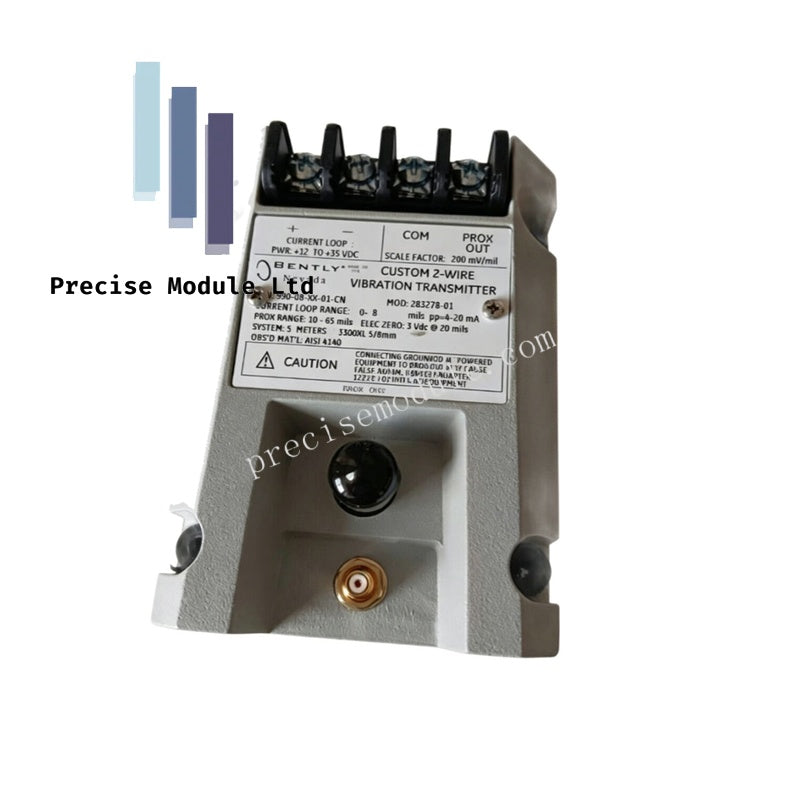
Bently Nevada 990-08-XX-01-CN 990 Vibration Transmitter
Bently Nevada 990-08-XX-01-CN 990 Vibration Transmitter
Manufacturer: Bently Nevada
Condition:in Stock
Product Type: Vibration Transmitter
-
Product Origin: USA
Payment:T/T, Western Union
-
Weight: 440g
Shipping port: Shanghai/Yiwu/Shenzhen
Warranty: 12 months
Share
Bently Nevada 990-08-XX-01-CN 990 Vibration Transmitter
The Bently Nevada 990-08-XX-01-CN, also cataloged as the 990 Vibration Transmitter, operates as a dedicated hardware component for conditioning eddy-current proximity probe signals into proportional current loops within machinery control and monitoring platforms.
Hardware Specifications
| Parameter | Specification |
|---|---|
| Model | 990-08-XX-01-CN |
| Brand | Bently Nevada |
| Origin | USA |
| Weight | 0.44 kg |
| Dimensions | 10.0 cm x 7.5 cm x 5.2 cm |
| Operating Temp | -35 deg C to +85 deg C |
| Power Consumption | Loop-powered (12 to 35 VDC input) |
| Input Compatibility | 3300 NSv proximity probe with matching extension cable (5 m or 7 m) |
| Output Signal | 4-20 mA DC proportional to peak-to-peak vibration amplitude |
| Diagnostic Interface | Non-isolated BNC coaxial connector and PROX OUT / COM terminals |
| Circuit Protection | Integrated Not OK / Signal Defeat loop suppression |
| Mounting Options | 35 mm DIN-rail clips or integrated bulkhead mounting screws |
Machinery Monitoring & TSI Characteristics
The transmitter functions natively as a proximity transducer interface, converting raw high-frequency RF signals into a linear voltage variation before rectifying it into a 4-20 mA current loop. During initialization and routine diagnostic sweeps, gap voltage validation targets a nominal -10 VDC baseline across the PROX OUT and COM terminals to verify the physical distance between the probe tip and the target shaft. This electrical offset isolation prevents cross-talk suppression failures across multi-axis arrangements and allows high-fidelity extraction of rotor dynamics via the unconditioned BNC port. If the probe gap exceeds calibrated physical limits or experiences a cable disconnect, the integrated Not OK circuit triggers immediately, clamping the loop output to prevent false machinery protection alarms.
Frequently Asked Questions
Q: Can the 990 transmitter be used with standard 3300 XL 8 mm proximity probes?
A: No. The internal driver circuitry of the 990 transmitter is specifically tuned and calibrated for the electrical characteristics of the 3300 NSv proximity probe and its corresponding 5-meter or 7-meter extension cable. Connecting mismatched probe diameters will cause incorrect eddy-current probe scaling and non-linear output errors.
Q: What is the exact function of the dynamic BNC connector during active plant operation?
A: The BNC port provides an unconditioned, raw voltage signal directly from the proximity probe. This allows diagnostic equipment, such as vibration analyzers or data acquisition systems, to capture raw peak-to-peak wave shapes and gap voltage values without disconnecting loop wiring or interrupting the primary 4-20 mA control path.
Q: How does the Not OK/Signal Defeat circuit respond during a total probe failure?
A: When the circuit detects an open loop, short circuit, or an out-of-range gap voltage condition, the 4-20 mA loop current is driven below 3.6 mA. This low current state signals the host control system that the transducer loop is invalid, suppressing downstream alarm logic to prevent false trips.
Field Installation Guidelines
- Enclosure and Environmental Shielding: Install the transmitter inside a sealed, dust-proof industrial enclosure to protect the non-interacting zero and span adjustment potentiometers from corrosive environmental particulates and moisture.
- Coaxial Cable Layout and Isolation: Ensure the coaxial cable connection from the 3300 NSv extension cable to the transmitter is tight and free of mechanical tension. Insulate the outer barrel of the coaxial connector to prevent accidental contact with the metal enclosure chassis, which can introduce ground loops and corrupt the vibration readings.
- Shield Termination and Grounding: Terminate the outer shield of the 4-20 mA loop signal cable at a single point, preferably at the control system cabinet ground rack. Do not ground the shield at both ends to prevent circulating ground currents from introducing signal noise into the diagnostic telemetry.
- Conduit Routing Constraints: Route the low-voltage sensor input wiring and the 4-20 mA loop wiring in dedicated, grounded metal conduits separated from high-voltage AC power distribution lines or variable frequency drive (VFD) output cables to minimize electromagnetic interference.
Hot Tags :


- Choosing a selection results in a full page refresh.
- Opens in a new window.