


Honeywell
📢 100% genuine, extensive in-stock inventory, fast shipping!
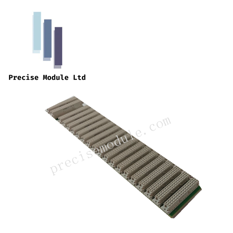
Honeywell 10315/1/1 Redundant I/O Backplane
Honeywell 10315/1/1 Redundant I/O Backplane
Manufacturer: Honeywell
-
Product No.: 10315/1/1
Condition:in Stock
Product Type: Redundant I/O Backplane
-
Product Origin: USA
Payment:T/T, Western Union
-
Weight: 1000g
Shipping port: Shanghai/Yiwu/Shenzhen
Warranty: 12 months
Share
Honeywell 10315/1/1 Redundant I/O Backplane
The Honeywell 10315/1/1, also cataloged as the 10315 redundant I/O backplane, serves as a base board PCB for housing and interconnecting redundant I/O modules within Honeywell rack-mounted control systems.
Hardware Specifications
| Parameter | Specification |
|---|---|
| Model | 10315/1/1 |
| Brand | Honeywell |
| Origin | U.S.A |
| Weight | Not specified |
| Dimensions | 19-inch rack, 3 HE (3U), 84 TE width |
| Operating Temp | 0 deg C to 60 deg C (32 F to 140 F) |
| Chassis Material | Chrome-plated steel (EMI shielding) |
| Power Supply | 24 VDC integrated busbar |
| Current Consumption | Passive backplane (none) |
| Max Current (Faston) | 10 A |
| Max Current (I/O Pin) | 2 A |
| Isolation | Channel-to-channel isolation built-in |
| I/O Capacity | 18 slots (positions 1–18) |
| Bus Drivers | Slots 20 and 21 for HBD 10100/2/1 |
| I/O Connectors | CN1, CN3, CN5, CN7, CN9, CN11, CN13, CN15, CN17 |
| Programming Ports | P1 through P17 (odd numbers only) |
Channel-to-Channel Isolation and Bus Integrity
The 10315/1/1 backplane enforces channel-to-channel isolation across all I/O slots, preventing electrical interference between modules. Dedicated bus driver slots (20 and 21) maintain deterministic communication across the horizontal bus. EMI shielding via chrome-plated steel chassis ensures stable operation in industrial environments, reducing susceptibility to noise coupling.
Frequently Asked Questions (FAQ)
Q: How many I/O modules can be installed in the 10315/1/1 backplane? A: Up to 18 modules can be installed across slots 1–18.
Q: What is the maximum current supported per connector pin? A: Each I/O connector pin supports up to 2 A, while Faston pins support up to 10 A.
Q: Does the backplane consume power itself? A: No. It is a passive PCB; power is distributed via the integrated busbar.
Field Installation Guidelines
- Mount securely in a 19-inch rack with 3U clearance.
- Ensure grounding continuity between chassis and cabinet earth bus.
- Route signal wiring separately from high-voltage conductors to minimize EMI.
- Verify bus driver modules are installed in slots 20 and 21 before energizing.
- Inspect connector seating and shielding integrity prior to commissioning.
Hot Tags :


- Choosing a selection results in a full page refresh.
- Opens in a new window.