


Honeywell
📢 100% genuine, extensive in-stock inventory, fast shipping!
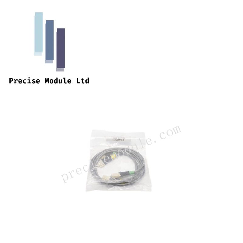
Honeywell 51202343-001 Power Supply Status Indication Cable
Honeywell 51202343-001 Power Supply Status Indication Cable
Manufacturer: Honeywell
-
Product No.: 51202343-001
Condition:in Stock
Product Type: Power Supply Status Indication Cable
-
Product Origin: USA
Payment:T/T, Western Union
-
Weight: 260g
Shipping port: Shanghai/Yiwu/Shenzhen
Warranty: 12 months
Share
Honeywell 51202343-001 Power Supply Status Indication Cable
The Honeywell 51202343-001, also cataloged as the 51202343 Status Indication Cable, operates as a multi-conductor assembly for transmitting power supply condition signals within Honeywell control system enclosures.
Hardware Specifications
| Parameter | Specification |
|---|---|
| Model | 51202343-001 |
| Brand | Honeywell |
| Origin | USA |
| Weight | Approx. 260 g (0.57 lbs) |
| Dimensions | Standard length 12 ft (3.66 m) |
| Operating Temp | -40 to +85 deg C |
| Storage Temp | Not specified |
| Relative Humidity | Up to 95%, non-condensing |
| Power Consumption | Passive cable |
| Core Performance | 4-pair (8 conductors), 22 AWG twisted pair, PVC jacket |
4-20 mA HART Loop Protocol and Cold Junction Compensation
The cable is designed for integration with Honeywell Series C and TDC 3000 systems, supporting signal transmission loops at nominal 24–30 VDC. Heavy EMI/RFI shielding ensures stable communication in high-noise industrial environments. Channel-to-channel isolation is achieved through twisted pair geometry, while cold junction compensation (CJC) principles are maintained for accurate signal integrity across extended cabinet routing.
Frequently Asked Questions
Q: Can the 51202343-001 be used in hazardous area installations? A: No, this variant is UL Listed for general industrial use but does not include intrinsic safety barriers.
Q: How should shielding be terminated during installation? A: Shielding must be grounded at the cabinet termination point only to prevent ground loop currents.
Q: What is the maximum continuous current supported? A: The cable supports up to 1.0 A continuous current per conductor set.
Field Installation Guidelines
- Route cables separately from high-voltage conductors to minimize EMI/RFI interference.
- Ground shielding at the cabinet termination point only.
- Verify insulation resistance (>100 MΩ at 500 VDC) before commissioning.
- Secure cable routing to prevent mechanical stress or bending beyond manufacturer specifications.
- Confirm continuity and conductor resistance (<0.1 ohms) during installation checks.


- Choosing a selection results in a full page refresh.
- Opens in a new window.