

Honeywell
📢 100% genuine, extensive in-stock inventory, fast shipping!
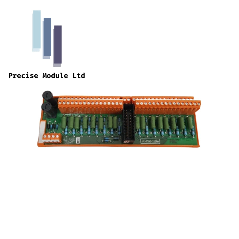
Honeywell FTA-T-18 Digital Input Module
Honeywell FTA-T-18 Digital Input Module
Manufacturer: Honeywell
-
Product No.: FTA-T-18
Condition:in Stock
Product Type: Digital Input Module
-
Product Origin: USA
Payment:T/T, Western Union
-
Weight: 300g
Shipping port: Shanghai/Yiwu/Shenzhen
Warranty: 12 months
Share
Honeywell FTA-T-18 Digital Input Module
The Honeywell FTA‑T‑18, also cataloged as the FTA‑T‑18 digital input module, operates as a discrete 24 VDC field‑signal acquisition card for controller backplane routing within Honeywell process‑control platforms.
Hardware Specifications
| Parameter | Specification |
|---|---|
| Model | FTA‑T‑18 |
| Brand | Honeywell |
| Origin | Honeywell process‑control systems |
| Weight | 0.3 kg (0.87 kg packaged) |
| Dimensions | 100 mm × 80 mm × 40 mm |
| Operating Temp | –40 deg C to +85 deg C (cabinet‑dependent limits typically 0 deg C to 60 deg C) |
| Power Consumption | 24 VDC / 20 mA per loop |
| Input Voltage | 24 VDC nominal |
| Input Current | 20 mA per loop |
| Output Logic | 24 VDC / 20 mA routing |
| Channel Count | 16 discrete inputs |
| Isolation | Full galvanic isolation between field loops and controller backplane |
| Mounting | DIN rail or panel mount |
Channel‑to‑Channel Isolation in Honeywell Discrete Input Cards
The module applies galvanic isolation across all 16 field loops, preventing inductive spikes from propagating into the controller backplane. This isolation behavior aligns with Honeywell’s broader process‑control design practices, including predictable boundaries used in 4‑20 mA HART loop protocol and Fieldbus/Profibus gateway modules. The fail‑safe execution path forces associated registers to a low‑potential state during wire breaks or circuit faults, enabling deterministic trip behavior.
Frequently Asked Questions
Q: Does the module support hot‑swap during operation? A: No. Removal or insertion must be performed during a controlled shutdown to avoid backplane disturbance.
Q: How does the module react to field‑wire breaks? A: The fail‑safe mechanism drives the affected register to a low‑potential state to trigger immediate trip logic.
Q: Are the 16 channels electrically isolated from each other? A: Yes. Each loop is galvanically isolated from adjacent channels and from the controller backplane.
Field Installation Guidelines
- Maintain correct polarity on all 24 VDC field loops before energizing.
- Segregate discrete wiring from high‑voltage conductors to reduce inductive coupling.
- Ensure DIN rail or panel mounting provides mechanical stability under vibration.
- Verify isolation and fail‑safe behavior using system diagnostics after installation.
- Keep ambient temperature within cabinet‑rated limits to avoid thermal drift.
Hot Tags :
- Choosing a selection results in a full page refresh.
- Opens in a new window.